Do you hate it when someone steals from you? Personally, I find it rather irritating. However, there have been instances of thieves visiting our apartment building’s underground garage. And thieves do what they do, so things go missing from storage rooms. As a result, I decided to design a door-mounted alarm system that would notify me via SMS whenever someone attempted to open my storage door. By combining various components such as an LTE module, a USB-C charging circuit, a SIM card, rechargeable Li-ion batteries, a microcontroller, and a siren, this system is capable of alerting users via SMS in the event of unauthorized access to their storage room. This alarm not only informs me when thieves are checking the storage rooms but also enables me to respond quickly if someone breaks into the storage room. Therefore, I invite you to continue reading and examine the electrical circuit in detail.
System overview
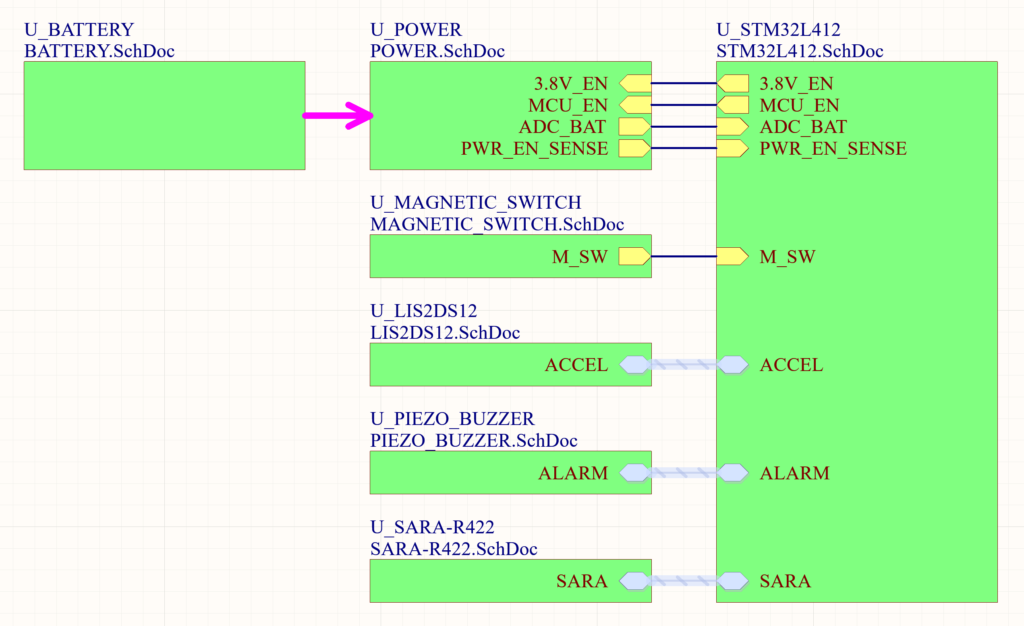
First, we’ll delve into the system as a whole, followed by a detailed examination of its individual components. Let’s begin with the top-level schematic sheet, shown in Figure 1, to better comprehend what makes up the entire system.
There is no electricity in the storage room; the security system operates solely on batteries, necessitating a design that minimizes power consumption. Most components in the system will be in sleep mode and will only wake up when an interrupt event occurs. To enhance convenience, the device is equipped with a USB port for recharging the batteries.
The system also includes an accelerometer. It is used to detect any attempts at opening the door. However, relying solely on the accelerometer does not provide precise information regarding whether the door has actually been opened or if someone is merely attempting to open it. To address this issue, a magnetic sensor, along with a magnet, is used to indicate the actual opening of the door.
In order to scare off thieves, the security system is equipped with a siren that will activate when the alarm is armed and the door is opened.
The entire system is controlled by a microcontroller, which establishes communication with the user through the LTE module.
Having already covered the system as a whole, we can now proceed to explore its individual components in greater detail.
Battery charging
When selecting a battery charging chip for this storage security alarm project, the MAX77757 chip stood out as the ideal choice. Given that the batteries are integrated into the device, fast charging capability is essential. The MAX77757 chip excels in this aspect and proves to be an excellent option. One of its notable features is the adaptive input current limit, which eliminates concerns about voltage collapse or folding back when using a weak adapter. Additionally, the chip offers Type-C power source detection and integrates BC1.2 detection through the D+ and D- pins. Furthermore, the MAX77757 incorporates a battery true-disconnect FET, allowing precise control over battery charging, discharging, and isolation in the event of a fault. With these impressive features, the MAX77757 chip provides the necessary functionality and safety measures for our storage security alarm system.
The battery charging design shown in Figure 2 is relatively straightforward. To achieve the maximum fast charge current of 3.15A, a 24.9kΩ resistor is connected from IFAST to GND. It’s important to note that the charging current also relies on the USB power source. If a weak USB source is used, the current will be adjusted according to the capabilities of the USB source.
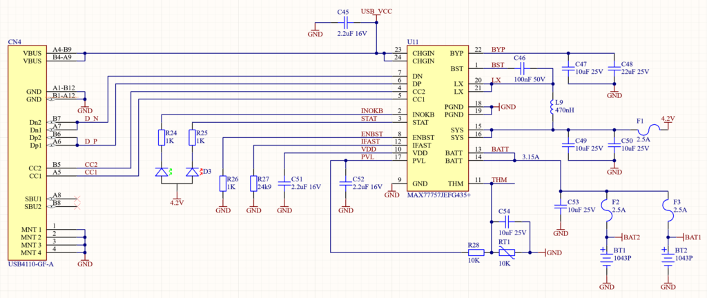
Another important aspect that I would like to highlight is temperature protection. The MAX77757 chip actively monitors the battery temperature through the utilization of an NTC thermistor connected to the THM pin. It intelligently adapts the fast-charge current or charge termination voltage based on the fluctuating battery temperature, ensuring optimal charging conditions.
Furthermore, the battery charge level will be monitored by the microcontroller. To accomplish this, a voltage divider will be used, allowing the microcontroller to measure the battery voltage using an ADC. Once the battery reaches a critical level, the microcontroller will notify the user through an SMS, indicating that it is necessary to recharge the batteries.
Power management
Designing a storage alarm system requires thoughtful attention to power management in order to achieve efficient operation and extend battery life. In this regard, the implementation of DC-to-DC converters proves to be a wise choice. By using these converters, the system can effectively regulate the voltage levels required by various components while enhancing power efficiency. Compared to traditional linear regulators, DC-to-DC converters offer higher efficiency levels, reducing power dissipation and increasing the overall runtime of the onboard battery. This is crucial for this project because the storage alarm system relies on battery power.
We have already talked about the battery charging circuit. However, we still need to talk about changing the battery voltage to the required voltage levels in the system. Within the system, two DC/DC converters are used for this purpose. The first converter transforms the battery voltage to 3.8V, meeting the specific requirements of the LTE module. The second converter steps down the voltage to a precise 1.8V, fulfilling the power needs of the microcontroller and other interconnected chips. The integration of these DC/DC converters, along with the previously discussed battery charging and power path management circuit, forms a comprehensive power management solution for this project.
LTE module
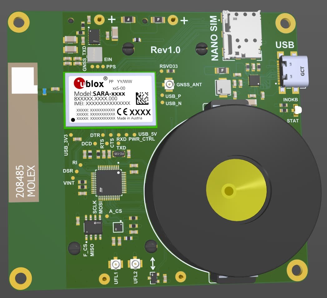
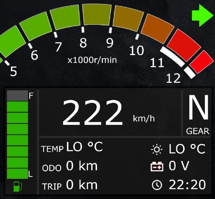
SARA-R4 is an ultra-compact LTE-M, NB-IoT and EGPRS module for multiregional use. The variant that I decided to use is the SARA-R422M10S. It is pre-integrated with the u-blox M10 GNSS receiver chip. SARA-R422M10S includes a separate GNSS antenna interface, which provides highly reliable and accurate positioning data simultaneously with LTE communication. In addition, the module offers unique hybrid positioning, in which the GNSS position is enhanced with u-blox CellLocate® data, providing location always and everywhere. Well, in this project, GNSS functionality is not required, but I am designing a motorcycle digital instrument cluster where I need a tracking function. That’s why I used this module in this project. As people say, two birds with one stone.
The circuit (Figure 3) of the SARA-R422M10S is relatively simple, yet it involves quite a few connections. The main components of the LTE circuit are the SIM card and antenna.
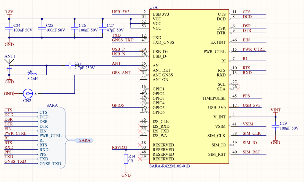
For the project, I opted for a removable SIM card due to its simplicity. The SIM card holder that I chose has 6 contacts and 2 additional pins relative to the mechanical switch integrated in the SIM connector for mechanical card presence detection. Connecting the SIM card is a straightforward process, but two factors are crucial: RF coupling and ESD protection. To prevent RF coupling, a 47 pF bypass capacitor is placed on each SIM line. And to protect the LTE module from static discharge, a low capacitance TVS diode is placed on all of the SIM lines. Both capacitors and TVS diodes are placed very close to each related pad of the SIM connector. Of course, a 100 nF bypass capacitor on the SIM supply line is placed to prevent digital noise.
Among the crucial aspects, one that stands out as highly significant is the antenna. The SARA-R4 series modules provide an RF interface for connecting an external cellular antenna. The ANT pin serves as the primary RF input/output, enabling the transmission and reception of cellular RF signals. In this project, I am using an integrated ceramic SMT antenna. The ANT pin has a nominal characteristic impedance of 50 and must be connected to the antenna through a 50 ohm transmission line to allow clean transmission/reception of RF signals. Moreover, the antenna connection requires suitable matching components. I’m using the suggested values from the antenna datasheet. Ideally, a test should be performed with a vector network analyzer to pick the right values required for my board.
Accelerometer
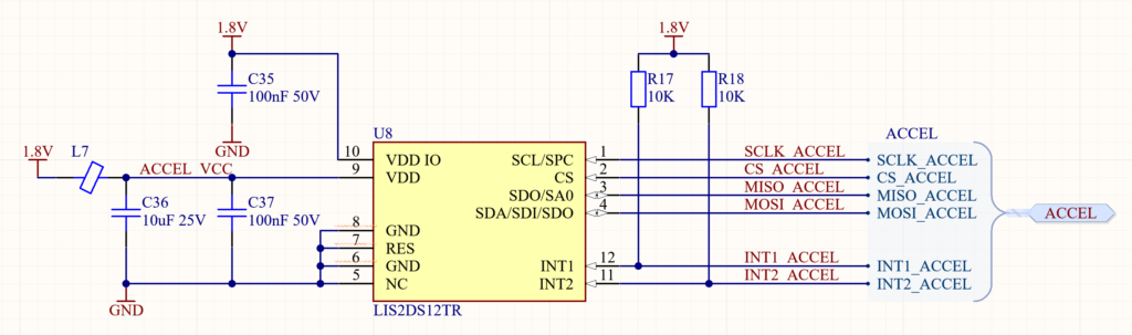
To identify attempts at opening the door, I opted to use an accelerometer capable of generating interrupts for specific events. Also, as already mentioned, the system runs on batteries, so power consumption is very important. Hence, I chose LIS2DS12 for this project. The LIS2DS12 is an ultra-low-power three-axis linear accelerometer. When the activity recognition function is activated, the LIS2DS12 is able to automatically wake up as soon as the interrupt event has been detected. Configurable interrupts on this accelerometer allow me to put the entire system to sleep and leave only the accelerometer and power circuits active. Upon detecting any movement, the accelerometer can wake up the microcontroller, which can then alert the user regarding the potential theft risk.
The accelerometer circuit is quite simple, as seen in Figure 4. Aside from the bypass capacitors, the electrical circuit comprises connections for SPI communication and interrupt pins.
Siren
For the alarm siren, I use an externally powered piezo buzzer. A piezo buzzer is an electronic device used to generate sound. When an alternating current is applied to a piezoelectric element, such as a ceramic disc, it undergoes rapid expansion and contraction, creating vibrations that produce sound. My selected buzzer is able to create more than 90 dBA output at 3 meters.
Externally driven buzzers need a piezo driver. In this particular project, I have chosen to use the DRV2700. The DRV2700 is specifically designed for driving piezo loads. It is a single-chip piezo driver with an integrated 105V boost switch, power diode, and fully differential amplifier. The circuit for the DRV2700 can be seen in Figure 5. Now, let’s explore this circuit in detail.
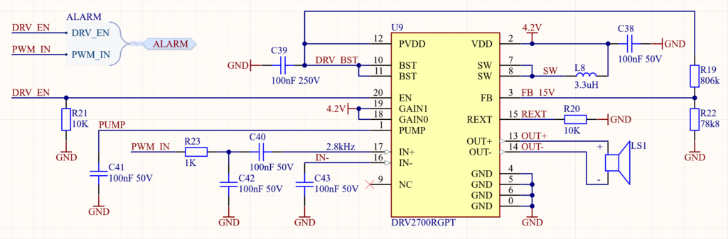
I am using an AC coupled single-ended PWM to drive the DRV2700. On the input, a first-order RC filter is used to ensure the higher frequencies have been attenuated and are not amplified. The DRV2700 has programmable gains through the GAIN[1:0] bits. Here, I set the highest gain possible. The boost voltage is set to 15V using two external resistors (R19 and R22). The current limit of the boost switch is set through a resistor to ground placed on the REXT pin (R20). The current is set so that it is less than the rated saturation limit of the inductor.
Magnetic sensor
To track the position of the storage door, I will use a magnet and a magnetic sensor. Specifically, I have opted to use the RR122-1B12-511, which is a digital push-pull magnetic sensor. This sensor operates as an active magnetic sensor and has an extremely low average current drain of approximately 50nA. Therefore, it is highly suitable for applications involving battery-powered electronics.
The output voltage on the RR122-1B12-511 is active low, meaning that while a sufficiently strong magnetic field is present, the output voltage is low. The circuit for RR122-1B12-511 is shown in Figure 6.
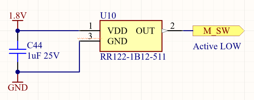
The circuit, as is evident, is remarkably simple and consists of only two components. Besides the sensor itself, the circuit includes only a bypass decoupling capacitor, which is positioned between the supply voltage and ground. Furthermore, the output voltage is connected to a digital input pin on a microcontroller.
MCU
Designing a storage alarm system requires careful consideration of various components, and one crucial aspect is selecting the right microcontroller. In this regard, the STM32L412 emerges as an ideal choice due to its high performance and ultra-low-power capabilities. The foremost requirement for the storage alarm system is to run for a long time from its onboard battery. This necessitates a microcontroller that can deliver optimal power efficiency. The STM32L412 meets this requirement by offering remarkable power-saving features. By utilizing this microcontroller, the storage alarm system can effectively conserve energy while ensuring reliable performance.
While the microcontroller plays one of the most important roles in the design of the storage alarm system, I have decided not to delve into its circuit in this blog post. It is likely that you have come across numerous microcontroller circuits in the past, and this particular design does not offer any groundbreaking features worth highlighting. The circuit primarily consists of standard components such as bypass capacitors and connections, which have already been discussed in previous sections.
Summary
In this article, we explored the design of a storage alarm system aimed at preventing theft and unauthorized access to storage rooms. The system incorporates various components, including an LTE module, USB-C charging circuit, SIM card, rechargeable Li-ion batteries, microcontroller, and siren, to create a robust security solution. By combining these elements, the system can alert users via SMS whenever someone attempts to open their storage door, enabling a quick response to a potential break-in.
In the next part of this project, we will explore the design of the printed circuit board (PCB), providing further insights into the implementation of the storage alarm system. Stay tuned for an in-depth examination of the electrical circuitry and layout of the PCB.
Do you want to learn more about PCB design? Join us in Part 2 to continue the journey.