An analog to digital converter (ADC) takes an input voltage and produces a binary output code. This output code is directly proportional to the input voltage. A binary code is made up of two digits, also known as bits, 0 (zero) and 1 (one). The number of bits depends on the resolution of the ADC. Typically, a decimal number is used to express the ADC output code. Although most modern microcontrollers come with built-in ADC converters, external ADCs are also used. In this article, we will go over how to convert an ADC digital code to a voltage value.
Analog to digital conversions are dependent on the ADC reference voltage and resolution (bit number). The ADC reference voltage can vary and depends on what is connected to the reference voltage pin. The resolution is stated in the ADC datasheet.
The formula to convert the result of an ADC output code into a voltage can be expressed as:
$$Voltage= \frac{ADC_{code}\cdot ADC_{reference}}{2^{Bits}}$$
Example of how to convert an ADC code to a voltage
Assume we have an 8-bit ADC connected to a microcontroller. The ADC’s reference voltage is 3.3V. The output code of the ADC is 178, or 10110010 in binary. We may use the formula above to determine the voltage that we measured:
$$\frac{178\cdot 3.3V}{2^{8}}= 2.295V$$
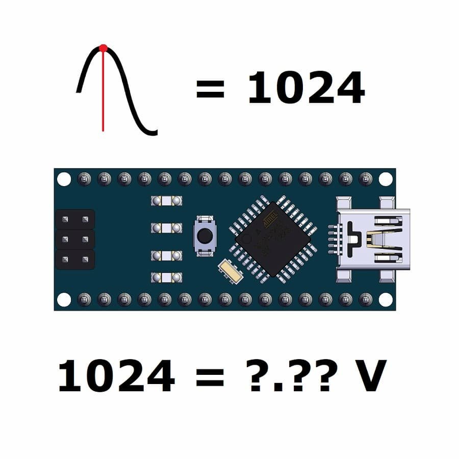
Arduino nano ADC code to a voltage conversion example
Now imagine that we are using the Arduino Nano to build a project and that we want to read analog voltage. The Arduino Nano development board is based on the ATmega328P microcontroller. According to the first page of the datasheet, the ATmega328P has 10 bit resolution (Figure 1).

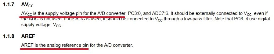
On the fourth page of the datasheet, we can find that the AVCC pin is the supply voltage and that the AREF pin is the analog reference for the ADC (Figure 2).
Internal reference voltages of 1.1V or AVCC are provided on-chip, according to information on page 205 (figure 3).

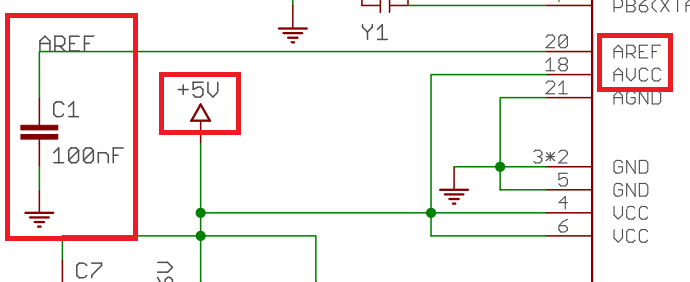
We can see from the Arduino Nano schematics that the AVCC pin is connected to 5V and the AREF pin is decoupled by a capacitor (Figure 4).
We will assume that the ATmega328P is configured to use AVCC as an ADC reference voltage. Therefore, 5V is the ADC reference voltage. To convert the Arduino Nano ADC code to a voltage, we can rewrite the first equation to:
$$Voltage= \frac{ADC_{code}\cdot 5V}{1024}$$
The equation above can be used to convert the ADC output code into a voltage when reading the Arduino Nano ADC. For instance, if the ADC output is 952, the input voltage can be calculated as follows:
$$\frac{952\cdot 5V}{1024}= 4.648V$$