A single axis accelerometer is a device that measures acceleration in one direction. It is typically used to measure acceleration along a single axis, such as up and down or left and right.
Output of an accelerometer
An accelerometer measures acceleration. It can sense both static and dynamic forces of acceleration. In a static condition, it measures the gravity acceleration (1g). The gravity vector is aligned along the vertical and pointing towards earth (down). In dynamic conditions, an accelerometer also senses vibrations and movement. The output of an accelerometer is proportional to the acceleration it senses. Depending on the type of accelerometer, this output can either be digital or analog.
Single Axis Tilt Calculation
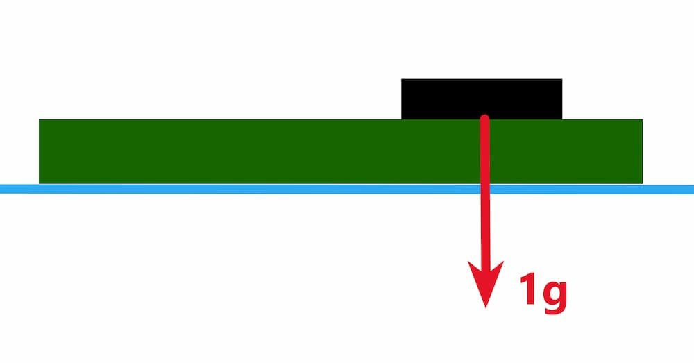
Let’s analyze a situation where we need to calculate the tilt angle of an object. Imagine a single axis accelerometer mounted on a printed circuit board (PCB) in a horizontal plane perpendicular to gravity, as shown in Figure 1. Here, the gravity force acts on the accelerometer, and the gravity vector is aligned along the vertical.
Now let’s imagine that we tilt the PCB with the accelerometer by α degree, like in Figure 2. Here, rotation is done only about the single axis. Any rotation about the other axes would reduce the magnitude of the acceleration and increase the error in the calculation.
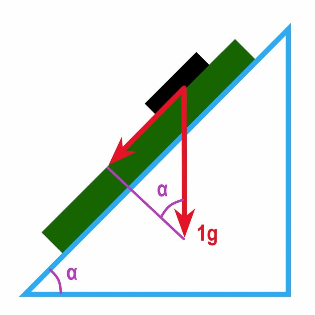
Since we can sense only one axis, we need to use the gravity vector to calculate the angle of inclination. The amplitude of the sensed acceleration changes according to the sine of the angle between the sensing axis and the horizontal plane. We can write this relationship as follows:
$$A= g\cdot sin\left ( \alpha \right )$$
Here, A is the measured acceleration, g is the gravity vector, and α is the tilt angle. The A is the difference between acceleration at the new position and acceleration at the reference position.
The sensor, of course, gives us the amplitude of acceleration. Then the inverse sine function can be used to calculate the tilt angle, as shown below:
$$\alpha= arcsin\left ( \frac{A}{g} \right ) $$
The result will be the angle of inclination in radians. To convert to degrees, multiply the result by 180/pi.
Limitations
The sine function is nonlinear; therefore, the relationship between A and α is nonlinear. If we plot the output acceleration versus the angle of inclination while rotating the accelerometer along a single axis, we would obtain a graph similar to that in Figure 3.
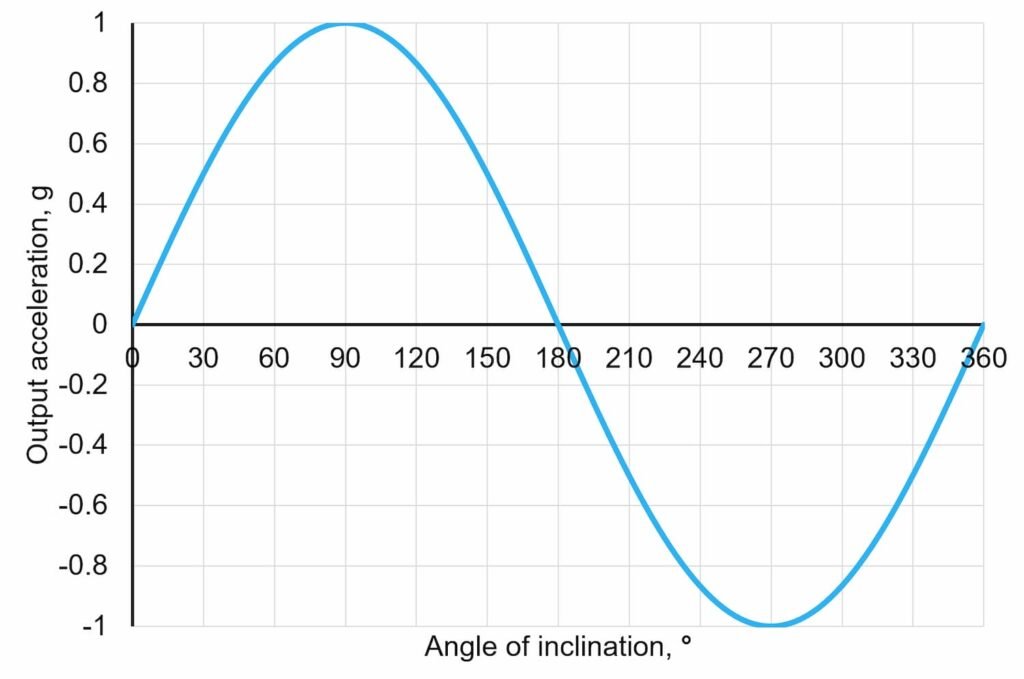
The sine function has good linearity from 0° to 45°, from 135° to 225°, and from 315° to 360°. However, we can also see that between +45° and +135° and between 225° and 315°, the tilt sensitivity decreases. Near ±90°, a large change in inclination results in a small change in output acceleration. Therefore, when the accelerometer signal is close to the +1g or -1g range, this method of measuring the angle of inclination is inaccurate.
Another disadvantage of the tilt measurement using a single axis is that it is impossible to distinguish between two tilt angles that produce the same sensor output. From Figure 3, we can see that, for example, from a 0.5g accelerometer output, it would be impossible to determine whether an accelerometer was tilted 30° or 150°.