Designing a user interface for a digital instrument cluster can be a challenging task, but it is essential to provide a user-friendly and intuitive interface that will allow riders to access all the relevant information. In the first blog post, we looked at the electrical connections in the original motorcycle instrument cluster. And in the second post, we spoke about the features we plan to include in our new digital instrument cluster. It is now time to discuss the user interface. Thus, in this blog post, we’ll go through how we created the user interface for our new instrument cluster.
The main screen
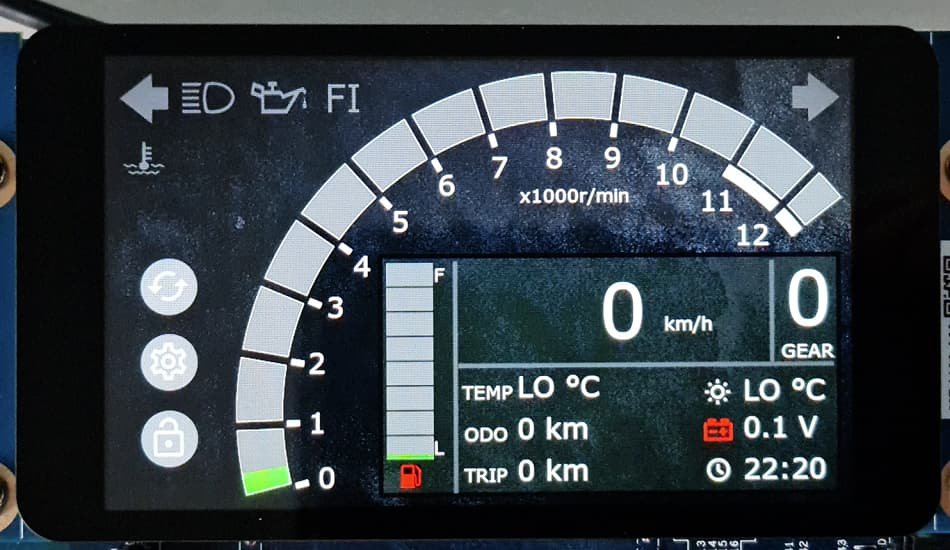
First and foremost, we wanted to ensure that the main window of our instrument cluster provides all the necessary information for driving. The main screen includes RPM, speed, odometer, trip, battery level, clock, engine temperature, ambient temperature, and gear position. In addition, we added indications for high beam, fuel level, FI, oil pressure, and right and left turn signals. By displaying all of these parameters on the main screen, riders will be able to monitor their motorcycle’s performance and stay informed about critical information while enjoying their ride. You can see the layout of the main screen in Figure 1.
The service window
In addition to displaying real-time information about the motorcycle’s performance, our digital instrument cluster will also provide riders with all the periodic service information we discussed in our second blog post. This information will include details about when the motorcycle needs its next oil change, brake pad inspection, chain lubrication, or other routine maintenance tasks. Figure 2 depicts the service screen layout.
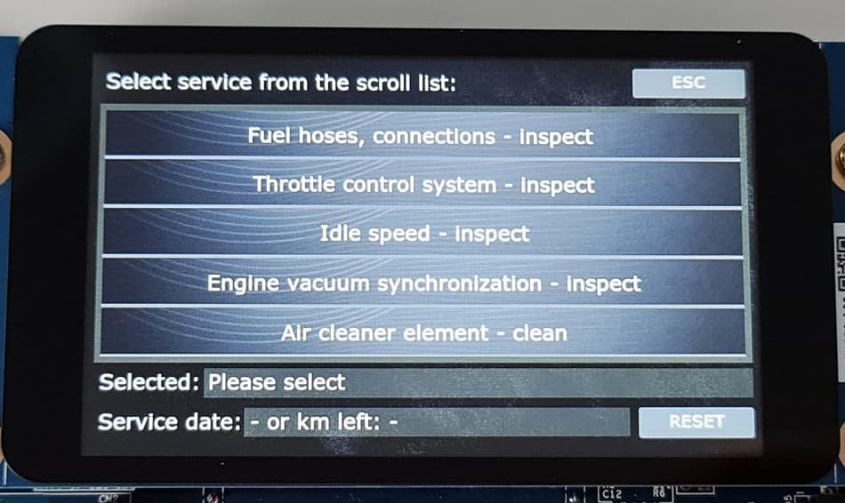
The instrument cluster will provide reminders for these tasks, ensuring that the driver does not miss any important maintenance schedules. By including this feature, we will help riders remember to take care of their motorcycle so it is well-maintained and in optimal condition. This will ensure a safe and comfortable ride.
The user setting window
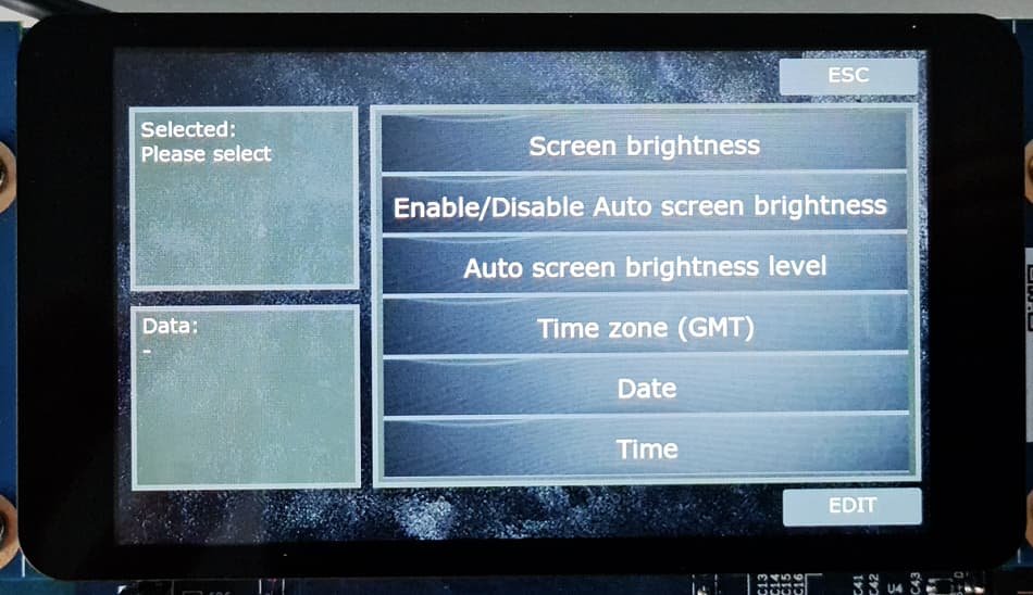
Our digital instrument cluster will also have a user settings window, shown in Figure 3, for further customizing. In this window, riders will be able to make modifications and tweaks to the instrument cluster based on their preferences. For example, users will be able to set the time and date, change the measurement units between metric and imperial, and set their contact information. In addition, the user will be able to choose which information to synchronize with data from the GPS.
The alarm setting window
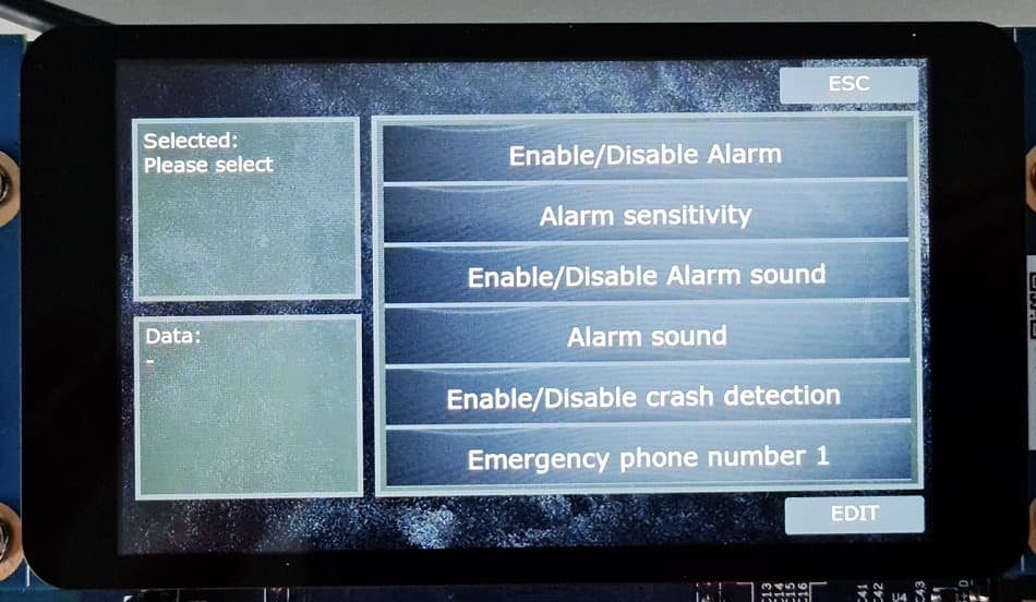
To enhance the safety and security of the motorcycle and its rider, our digital instrument cluster will also have an alarm. Figure 4 depicts the alarm settings window, where riders may make modifications and adjustments to the alarm settings based on their preferences. Users will, for example, be able to change the alarm sound, adjust the alarm sensitivity, and add or modify the contacts who will get an alert if the alarm is triggered. These settings will allow riders to personalize the alarm settings to their liking and guarantee that the alarm system is configured to meet their demands.
Pause for now
While designing the user interface for our digital instrument cluster is an essential part of the overall design process, we must suspend the user interface design at this point to create the instrument cluster schematic and PCB board. The schematic and PCB board design are critical components of the instrument cluster, as they determine how the hardware components will be connected and integrated into the system. By pausing the user interface design and focusing on the schematic and PCB board design, we can ensure that the hardware components are correctly integrated and the instrument cluster’s functionalities operate smoothly. Once the schematic and PCB board have been made, we can then resume the user interface design, incorporating the hardware components’ functionalities into the user interface design.
Come again
We hope you enjoyed reading about our progress on designing the digital instrument cluster for Kawasaki motorcycles. We’re excited about this project and can’t wait to share more updates with you. We invite you to follow our progress and stay updated on the latest developments by visiting our Instagram page. Here, you can find videos of the dashboard and more information about the progress we are making. We also welcome any questions or feedback you may have about the design process or our instrument cluster. We look forward to sharing more updates with you soon!