A photodiode is a light-sensitive semiconductor device with a p-n or p-i-n structure. A photodiode produces current when it absorbs photons (or light). We will discuss two operation modes of photodiodes: photovoltaic and photoconductive.
HOW PHOTODIODE WORKS
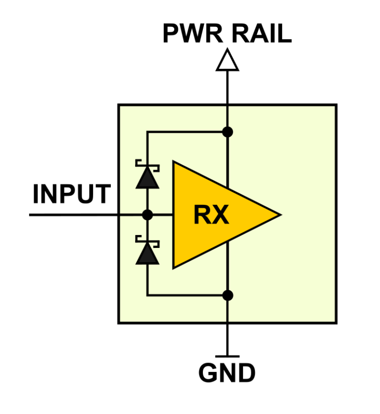
When a photon of sufficient energy strikes an atom within the diode, it releases an electron. This creates an electron–hole pair. Photons absorbed in the depletion region, or one diffusion length away from it, will create electron hole pairs that will move to opposite ends due to the electric field. Holes will move toward the anode, and electrons toward the cathode. These moving charge carriers form the current in the photodiode.
PHOTOVOLTAIC MODE
Photodiodes can be used without any voltage bias. Without added voltage across the junction, dark current can be very low. The major downfall with unbiased photodiodes is the slow response speed. Without bias voltage, the capacitance of the photodiode is at its maximum, leading to a slower speed. Another disadvantage of zero biased operation is the non-linear output of the photodiode with respect to the illumination. Photovoltaic mode is beneficial when a photodiode operates in low frequency applications that need to maximize low-illuminance performance.
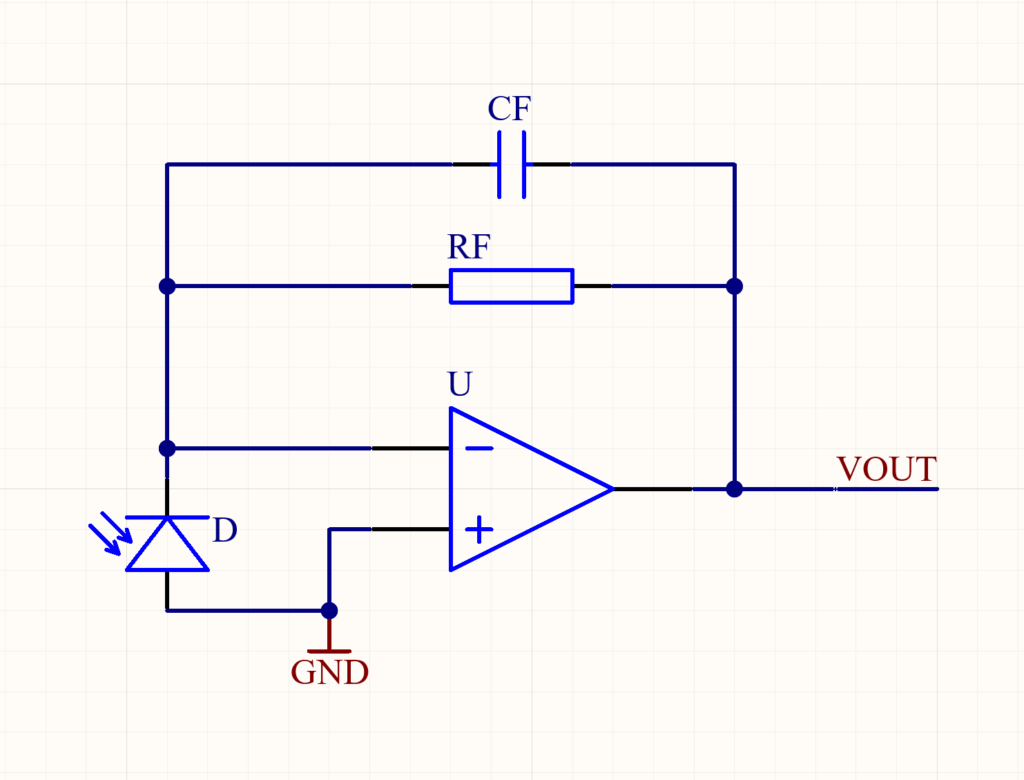
In the photovoltaic mode, transimpedance amplifiers are used as preamplifiers for photodiodes. Figure 1 shows a common circuit example of a photovoltaic implementation. This op-amp circuit is called a transimpedance amplifier. The transimpedance amplifier converts the photodiode’s current output signal to a usable voltage level. The current-to-voltage ratio is determined by the value of the feedback resistor RF. In the circuit, zero volts are held across the photodiode, since inverting and non-inverting operational amplifier inputs are held at the same potential by the operational amplifier. This minimizes the possibility of dark current. Photovoltaic mode is used in precision applications.
PHOTOCONDUCTIVE MODE
In photoconductive mode, the diode is reverse biased. This means that the cathode is driven positively with respect to the anode. The reverse bias causes the potential across the depletion region to increase and the width of the depletion region to increase. Due to this, the response time and junction capacitance will be reduced. Another benefit of reverse biased operation is the linear output of the photodiode with respect to the illumination. Unfortunately, increasing the bias voltage increases the dark current as well. Photoconductive mode is good for applications that need fast response time and more output signal relative to illuminance.
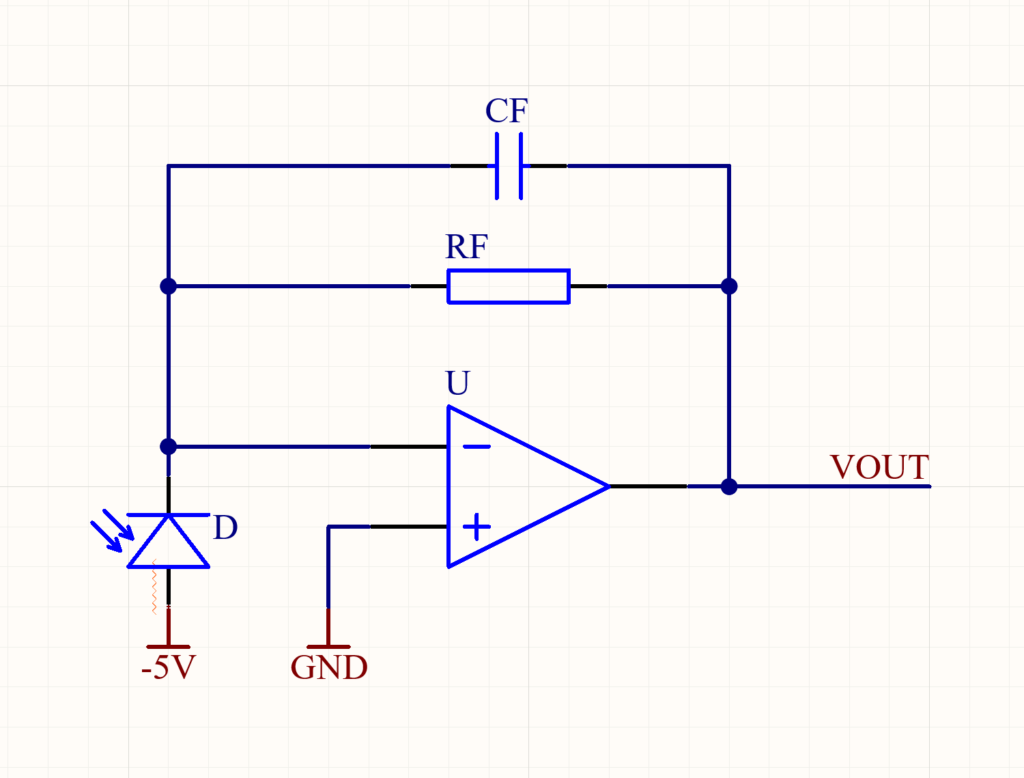
To operate a photodiode in photoconductive mode, we can take the circuit from Figure 1 and connect the photodiode’s anode to a negative voltage supply instead of ground (see Figure 2). In this case, the photodiode is reverse biased because the voltage at the cathode is higher than that at the anode. The circuit in Figure 2 is also called a transimpedance amplifier. The difference between this circuit and the circuit in Figure 1 is that the photodiode is reverse biased. This improves the bandwidth, increases sensitivity and lowers the junction capacitance, but we need to keep in mind that more reverse bias also increases dark current. The gain of the detector is dependent on the feedback resistor RF. This kind of circuit is used in high speed applications.
SUMMARY
We discussed photodiodes working in photovoltaic and photoconductive modes. Zero bias is used in photovoltaic mode, which minimizes dark current and also reduces noise. Photoconductive mode employs reverse biasing and gives wider bandwidth, higher sensitivity, and improved linearity, but also increases noise and dark current.