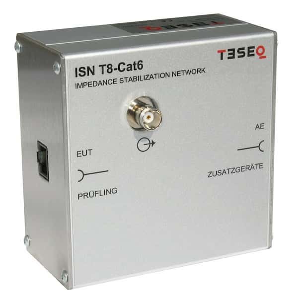
A while back, one of my devices failed the electromagnetic disturbances test. More specifically, there were problems with the conducted emissions on wired network ports in the frequency range from 150 kHz to 30 MHz. The device only passed for Class A. Pretty bummer situation considering the test cost me a small fortune. Figuring out what went wrong wasn’t a walk in the park either because the device used an Ethernet socket with integrated magnetics, so there were very few places where mistakes could be made. Anyway, an impedance stabilization network (ISN) was required to investigate the problem. Thus, in this blog post, I will tell you how I made an impedance stabilization network for two unscreened balanced pairs.
What is an impedance stabilization network?
An Impedance Stabilization Network (ISN) is a circuit designed to stabilize the impedance of a device or system at a specific frequency or over a range of frequencies. These ISN’s are used to perform conducted emissions measurements on signal and data cables. They are invasive transducers that must be connected in series with the conductors to be measured to standardize their CM and DM impedances. ISNs are designed to measure CM conducted emissions. CISPR 22 and CISPR 32 are common standards requiring the use of an ISN. You might have heard them called an asymmetric artificial network (AAN). That is because ISN’s are referred to as an asymmetric artificial network in CISPR 16-1-2.
The primary goal of an ISN is to provide a known and stable impedance at the input or output of a Device Under Test (DUT) so that accurate and repeatable measurements can be taken. In the context of EMC testing, it’s crucial to maintain a stable impedance to ensure that the test conditions are consistent and that the measured results are reliable.
There are different types of ISNs, and the specific design depends on the testing requirements and the standards being followed.
Why not just buy one?
First and foremost, certificated ISNs for EMC testing are expensive. These devices can cost several thousand dollars. So if you are on a budget, you can make something similar to those devices for around 50 dollars. Your DIY ISN will not be calibrated, but it will give you a rough idea of how close the device you are evaluating is to the EMC/EMI standard limits that you need to pass.
Additionally, bear in mind that laboratory EMC/EMI testing is expensive. The cost of these tests starts at tens of thousands of dollars. Therefore, if you measure and find problems in your device, you can fix them and thus save a lot of money on the EMC/EMI test that you would not have passed. Also, owning a device of your own will help you diagnose the problem easily.
Impedance stabilization network circuit
For my application, which is Ethernet, ISN for two unscreened balanced pairs was chosen. The ISN circuit that I chose is available in EN 55022 and is shown in Figure 2. Given that EN 55022 is a modified derivative of CISPR 22, the circuit in question is probably also present in CISPR 22.

This ISN can be used to measure common mode disturbances equally well on a single unscreened balanced pair or on two unscreened balanced pairs.
How does ISN with unscreened balanced pairs work?
The circuit shown in Figure 2 has two unscreened balanced pairs. Here, the signal passes through these pairs, and common mode noise is tapped off of them. Naturally, we will not avoid attenuation here. A center-tapped choke is provided to improve differential rejection. This choke is AC coupled to prevent DC loading. On its own, this would create an LC resonant circuit at a low frequency. To prevent this, a 390 ohm resistor is connected across the choke, which puts it approximately in critical damping. This, of course, puts some loads on the line itself, so the network will have one or two decibels of attenuation, and besides, we probably won’t avoid some reflections. So don’t expect excellent signal quality over this network.
Another thing is that wideband performance is most likely also poor. Since the inductance of transformers is high, long windings will be required to achieve this, and therefore propagation delay will cause impedance mismatch, dispersion, and reflections. Fortunately, the majority of long-distance communication methods that would be tested by this type of ISN have wide margins or are designed to work with these kinds of things anyway. For my application, it only needs to work up to 30 MHz for conducted emissions, so it should be fine.
DIY impedance stabilization network
From the given circuit, we see that four transformers (L1, L2, L3, and L4) are required. For each of them, I used the same T38 material core. The core I used had an inductance factor of 16 µH.
Details of transformer windings are given below:
- L1 was made with 6 strands of 0.15mm enameled wire. These wires were twisted in pairs. One pair was connected in parallel for the output winding. To wound the transformer, I used 9.5 turns around the core.
- L2 was made with 4 strands of 0.15mm enameled wire. These wires were also twisted in pairs. Here, I also used 9.5 turns.
- L3 and L4 are identical, and each is made of two strands of 0.15 enameled wire. This time, I used 14 turns. L3 and L4 are connected as single center tapped windings.
To calculate the number of turns, I used a simple formula that uses a special parameter, AL – inductance factor of the core.
$$L=A_{L}\cdot N^{2}$$
Here:
L – inductance (nH)
AL – inductance factor of the core (nH/turns square)
N – number of turns of the coil
You can find more on this here.
When it came time to assemble the entire ISN, trust me when I say I didn’t overdo it. Nope, I just grabbed whatever parts were lying around and put them together as quickly as possible. Winding the transformers took the most time, as it was necessary to prepare the twisted pair windings. Take a look at Figure 3 and 4 to catch a glimpse of what I put together.
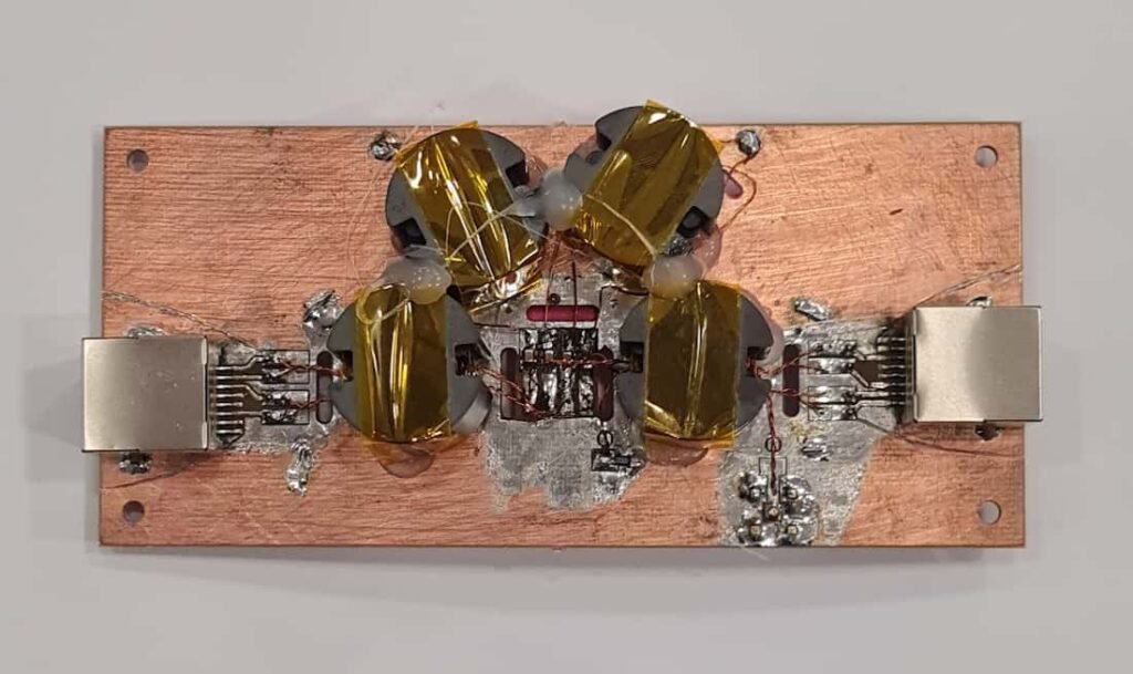

Now, I won’t lie, the hand made copper cuts on the laminated board might not win any beauty contests. I mean, I probably could’ve put in a bit more effort, but hey, it’s a fast one-off prototype, and it turned out pretty well considering the rush job. Of course, a touch of hot glue was indispensable in holding everything together in one piece. DIY may not always be pretty, but it gets the job done, and that’s what matters, right? Of course, when completing the DIY ISN, you should also think about the metal box, which would help with the shielding of this device.
ISN testing
Unfortunately, I’ve got nothing fancy to show you here. Once I wrapped up putting together my ISN, the call was made to go ahead and buy a certified one. Therefore, I did not perform any tests on my ISN. But, during the test using the purchased certified ISN, I decided to throw in my homemade version for kicks. And guess what? Pleasant surprise: the results looked pretty much the same to the naked eye. So, I’d confidently say, if you’re not keen on dropping 5000 dollars on EMI testing equipment, a DIY ISN can be a real lifesaver for a quick EMI precompliance test. All it takes is around 20 dollars worth of materials and a couple of hours of your work, and you’re good to go.