In this blog post, we will explain how to design a circuit to directly monitor temperature using an NTC thermistor with an analog-to-digital (ADC) converter on any microcontroller like an Arduino or STM32.
What is a NTC thermistor
An NTC (Negative Temperature Coefficient) thermistor is a type of temperature sensor that exhibits a decrease in electrical resistance as the temperature increases. In other words, its resistance drops as the temperature rises. This unique characteristic makes NTC thermistors invaluable components in various temperature-sensing applications.
Due to their sensitivity and reliable performance, NTC thermistors are widely used for temperature measurement and control in various industries. They find application in temperature monitoring systems, thermostats, environmental monitoring devices, industrial processes, automotive applications, and more. Their compact size, cost-effectiveness, and compatibility with electronics make them a popular choice for integrating temperature sensing capabilities into electronic devices and systems.
In the context of microcontrollers like Arduino or STM32, NTC thermistors can be effectively integrated to measure temperature accurately. By interfacing them with analog-to-digital converters (ADCs), the varying resistance of the thermistor can be converted into corresponding digital values, allowing microcontrollers to interpret and process temperature information for further analysis or control purposes.
NTC thermistor circuit design
In this section, we will design an NTC circuit that is designed to measure PCB temperatures from 0°C to 100°C.
NTC thermistor circuit
The simplest circuit to measure temperature with a thermistor is to use the thermistor as part of a resistor divider circuit, as shown in Figure 1.
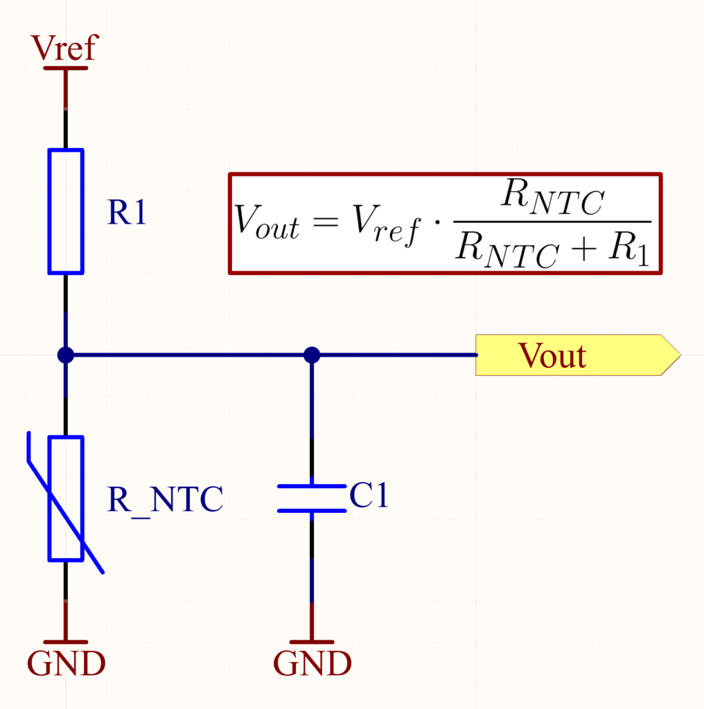
In this circuit, the NTC thermistor and the resistor form a voltage divider network. As the temperature changes, the resistance of the NTC thermistor varies, which in turn changes the voltage at the junction between the thermistor and the resistor. The voltage across R1 will increase as the temperature decreases, and conversely, the voltage across R1 will decrease as the temperature increases.
How to choose an NTC thermistor
Choosing the right NTC thermistor involves considering several critical factors to ensure accurate temperature sensing and optimal performance. Firstly, it’s crucial to assess the temperature range of your application and select an NTC thermistor with a resistance-temperature curve that suits this range. Thermistors come in different resistance values at a specific reference temperature (usually 25°C), so choosing one that aligns with your circuit and measurement range is essential.
Another important characteristic of a thermistor is its beta value (B). NTC thermistors are non-linear resistors that alter their resistance characteristics with temperature. The B constant describes the manner in which the resistance of a thermistor decreases. The B value is specified across a given temperature range and represents the change in resistance of the thermistor across that specified temperature range. In other words, B describes the steepness of the resistance-temperature curve. Beta is measured in degrees Kelvin (K) and is computed based on the formulation given below.
$$B=\frac{T_{1}\cdot T_{2}}{T_{2}-T_{1}}\cdot ln\frac{R_{1}}{R_{2}}$$
Also, consider the accuracy and tolerance of the thermistor. Thermistors with tighter tolerances offer more accurate temperature readings but can be more expensive.
In essence, selecting the right NTC thermistor involves a balance between temperature range, accuracy, sensitivity, and thermal response.
Practical example of how to select an NTC thermistor
So, as we mentioned earlier in this blog, we will design an NTC circuit that will be able to measure temperatures from °C to 100°C. Also, we’ll assume that we don’t need high accuracy, and any thermistor with better than 5 percent tolerance will do. There are many possible NTC options for this task. To find an NTC thermistor, I used TDK’s Chip NTC Thermistors Selection Guide. I chose a general-purpose NTC thermistor that has the NTCG164LH223HT1 manufacturer code. The NTC selected in this example is 22 kΩ at 25°C with a B(25/85) value of 4550K. Also, this thermistor has a 3% B value and resistance tolerances, which meet our circuit specification. As I mentioned, there are many NTC options that would be suitable for this task; this is just the first option that catches my eye.
Series resistor selection
Choosing the appropriate series resistor R1 value for the NTC thermistor is based on the temperature range monitored. In this case, it is from 0°C to 100°C. The tolerance for series resistor should be similar to the thermistor resistance tolerance. In this case, a readily available 1% tolerance resistor is sufficient. Of course, if your circuit requirements are higher, as with a thermistor, a better tolerance will be needed.
In order to choose the right value of R1, we need to find or calculate the resistance of the NTC thermistor at the two points specified in the task, i.e. at 0°C and 100°C. Fortunately, in our case, the datasheet provides a link to 1degC Step Data from -40℃ to 125℃. By downloading the CSV file from the link provided in the data sheet, we can find the resistances of the thermistor at 0°C and 100°C:
$$R_{0}=83.71k\Omega$$
$$R_{100}=1.009k\Omega$$
Now we can calculate R1 based on the expected maximum and minimum resistance of the NTC thermistor:
Series resistor selection using B value
Unfortunately, not all manufacturers provide detailed information, and often the NTC resistance at different temperatures is unknown. However, we can find NTC resistance based on temperature using the following formula:
$$R_{NTC}=R_{@298.15K}\cdot e^{B(\frac{1}{T}-\frac{1}{298.15K})}$$
Where:
- R(NTC) is the thermistor resistance (Ω) at temperature T;
- R(@298.15K) is the thermistor resistance (Ω) measured at 25°C given in the data sheet;
- B is the thermistor B value from data sheet in Kelvin (K);
- T is the temperature in Kelvin (K) that the thermistor is at (0°C + 273.15 = K).
As we can see from the equation, we encountered the first problem, in order to make calculations, we need B(0/100). Unfortunately, the datasheet of the thermistor usually does not specify it. In most cases, the data sheet has a specified value of B(25/85). As we previously mentioned, the NTCG164LH223HT1 B(25/85) value is 4550K. Using this value of B, we should get the resistance of the thermistor at the specified temperatures between the minimum and maximum resistance ranges specified in the data sheet.
We must not forget that the calculations use kelvins. So first we need to convert degrees to kelvins:
$$T_{min}=0^{\circ}C+273.15=273.15K$$
$$T_{max}=100^{\circ}C+273.15=373.15K$$
We can now calculate the thermistor resistances at these temperatures:
If we compare the calculated values, we can see that they fall within the min-max resistance range specified in the datasheet.
Now, as we did before, we can calculate R1 from the expected maximum and minimum resistance of the ntc thermistor:
From the results, we can see that the calculated resistance values in the first and second cases are different. For this reason, it is always better to use the manufacturer’s data, both for calculating circuit component values and for converting ADC values to temperature. Also, even though we got different values, they will not affect the measurement results because the selected value will be used in the calculations to convert the ADC values to temperature. What is important is that the output voltage of the circuit is between the input voltages of the ADC.
Output voltage of the NTC thermistor circuit
Let’s examine the output voltage range of our circuit using the calculated series resistance values. For this, we will assume that our reference voltage is equal to 3.3V. Our calculations will be based on the highest resistance of the NTC thermistor at 0°C and the lowest resistance value at 100°C, as provided in the datasheet: 89.75kΩ and 0.892kΩ respectively. By using these values, we will get the widest possible output voltage range for our circuit.
Using Ohm’s Law, we can calculate the output voltage of the voltage divider for both cases where the series resistance R1 is 9.2K or 9.65K. In the first case, we get that the output voltage will be between 0.292V and 2.993V. And in the second case, we get that the output voltage will be between 0.279V and 2.98V. You can see that in both cases, the output voltage between 0°C and 100°C will vary by 2.701V.