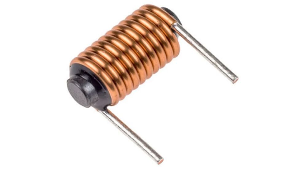
An inductor is an electrical component that stores energy in a magnetic field as current flows through it. Inductors are made of an insulated wire that is wound on different types of cores, which can be made of different materials. Many inductors have a ferromagnetic core (Figure 1), which serves to increase the magnetic field and thus the inductance. An inductor that doesn’t have a solid ferromagnetic core (Figure 2) is known as an air-core inductor. So, it does not depend upon a ferromagnetic material to achieve its specified inductance. Instead, it uses a magnetic field created by wire winding to store energy. Some inductors are wound without a bobbin and have just air as the core. Others are wound onto ceramic, plastic, or another non ferromagnetic type of bobbin. This article will discuss air core inductors and provide a step-by-step guide for creating one. From determining the inductor parameters to testing the finished product, we will guide you through the process and help you create an air-core inductor for your specific application.
Air core inductor application
Due to their unique characteristics, air-core inductors (shown in Figure 1) are frequently used in a wide range of electrical and electronic applications. They are perfect options when high linearity, high frequency, and low core loss are required.
Advantages of an air core inductor
- Saturation free.The current through an air-core inductor has no impact on the inductance of the coil. In contrast, the inductance of coils with ferromagnetic cores tends to peak at moderate field strengths before decreasing to zero as saturation gets closer.
- No iron losses. Air-core inductors are free of the “iron losses” that affect ferromagnetic cores. As frequency is increased, the air cores offer a higher quality factor (or Q), greater efficiency, greater power handling, and less distortion.
- High frequency operation. Air-core inductors can be designed to perform at frequencies as high as 1 Ghz.
Disadvantages of an air core inductor
- Larger size. Inductance tells how much energy could be stored in an inductor, and using ferromagnetic cores, this energy is significantly increased. Without a high-permeability core, more or larger turns are needed to achieve the required inductance.
- Greater radiation. Radiation is substantially smaller with the closed magnetic paths seen in cored inductors. The amount of loss from electromagnetic radiation will become significant as the diameter approaches a wavelength (lambda = c/f).
Single layer air core inductor (coil) design
Winding an air-core inductor is a relatively simple process. The hard part is determining inductor parameters such as the inductance, number of turns, coil diameter, coil length, and wire gauge. Usually, you’ll start by figuring out how much inductance your application requires. Then a wire gauge should be selected. It should be able to handle the current required for your application. Let’s now examine the method for calculating inductor parameters.
Air core inductor calculation
The calculation is based on Wheeler’s formula. This formula may be used to create an air-core, tightly wound, single-layer inductor like in Figure 2.

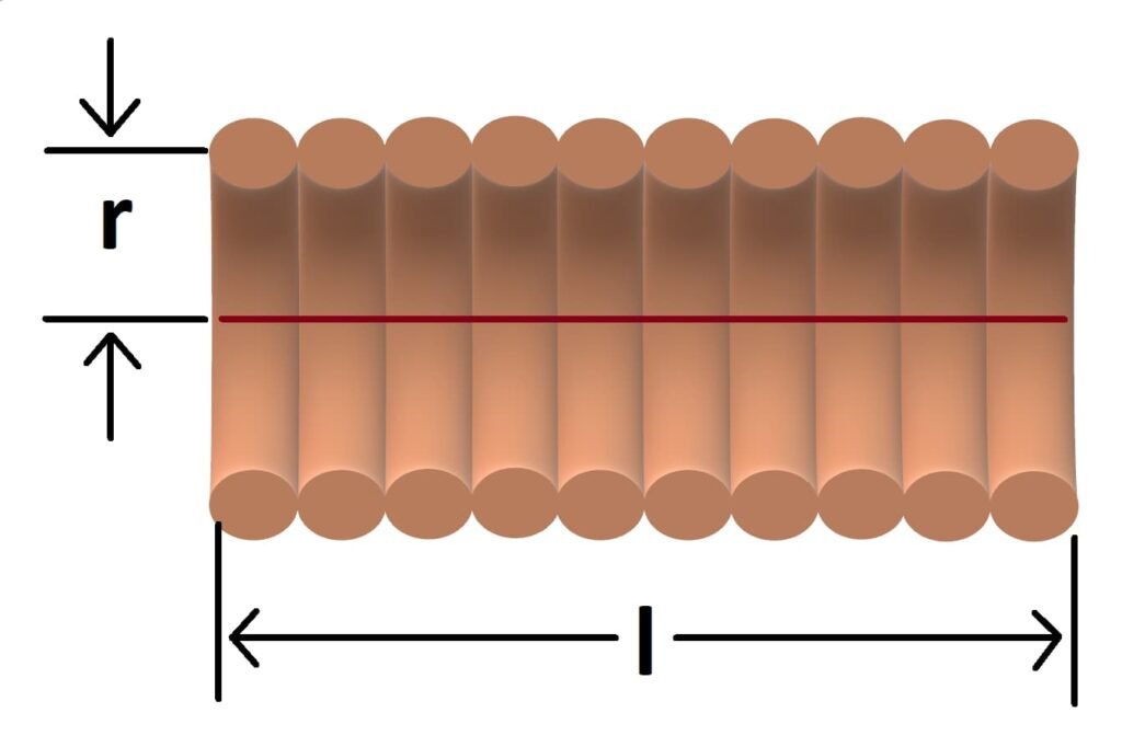
Wheeler’s inductance formula for single-layer wound coil (Figure 3) is provided below. The following formula is accurate to approximately 1% for 2r/l < 3.
$$L=\frac{N^{2}\cdot r^{2}}{9\cdot r +10\cdot l}$$
Where:
L – inductance in microhenry
r – radius in inches (measured from center of wire to the center of the coil)
l – length of the coil in inches
N – the number of turns
The formula above can be rewritten as follows:
$$N= \frac{\sqrt{L\cdot (9\cdot r+10\cdot l)}}{r}$$
If you insert each of the previously chosen parameters into the formula above, you should be able to calculate the number of turns you need. The length of your coil determines how many turns you need. Of course, you can just find and use some online calculators to determine the inductor’s parameters.
How to wind an air core inductor
Once you have the dimensions, you need to prepare the form that you’ll be winding the enameled copper wire around. The form diameter should be equal to the calculated coil diameter subtracted from the wire diameter. This can be a PVC pipe, a pen, or any other round item with the same diameter as what you determined.
Now it’s time to wind the copper wire. Start by wrapping the wire around the form, making sure to keep the turns close together and straight. When you reach the desired number of turns, you can slide the coil off the form. Alternatively, if the chosen winding form is not ferromagnetic, you can leave the coil on the form.
After you’ve finished winding the inductor, you need to prepare its leads so that it can be soldered to the printed circuit board (PCB). For this, you need to strip away the enamel and reveal the copper underneath it. For thicker wires it is easier to just scrape it off with a sharp knife. And for thinner wires, it is quite simple to remove the enamel by heating it with a soldering iron while simultaneously adding solder. Sometimes using a match or lighter to burn off the enamel does a wonderful job.
The last thing you should do is test the inductor using the LCR meter to ensure that it meets the required specifications. If not, adding or removing turns will change the inductance. Additionally, by moving the turns apart just a little bit, a small reduction in the inductance can be achieved.
Summary
Winding an air core inductor is a simple and straightforward process that requires only basic knowledge of electronics and the right materials. In this article, we showed you how to wind an air core inductor step by step. The process involves determining the inductor parameters, preparing the form to wind the wire around, winding the copper wire, preparing soldering leads, and testing the inductance of the inductor.