The first time you ever designed an electrical circuit for a car or motorcycle, you probably thought that the maximum voltage that your circuit would see was around 14.5 volts, which is the output of the alternator. In an ideal world, you would be right, but this world is not all roses. In this world, there is such a thing as automotive transient conditions. Under certain conditions, your circuit can see voltages as high as 100 volts. In this article, we will talk about transient conditions like reverse battery, cold crank, warm crank, and load dump. So read on to find out what to look for when designing automotive electrical circuits.
Reverse battery
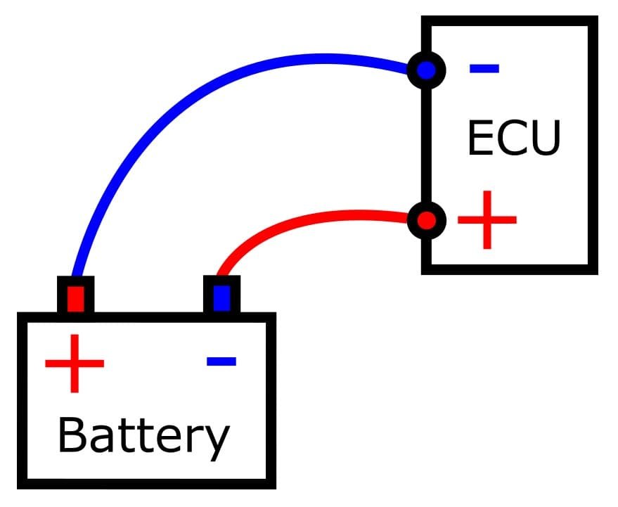
Reverse voltage can occur when the battery is disconnected from the vehicle and then accidentally reconnected incorrectly, mixing up the battery polarity, as in Figure 1. This results in a negative voltage across the power supply connection of the vehicle’s electronic control units (ECUs). Integrated circuits often have a negative voltage limit of just a few hundred millivolts.
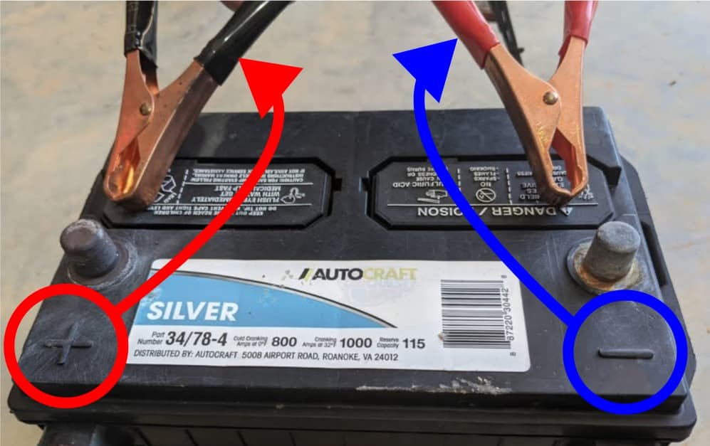
The electronics could also be damaged by reverse polarity if a jump-start is attempted with the jumper cables reversed, as shown in Figure 2. Without proper protection, the car’s electrical circuits would be burned in the event of a reverse battery condition. So it’s probably a good idea to double-check the cables before connecting them.
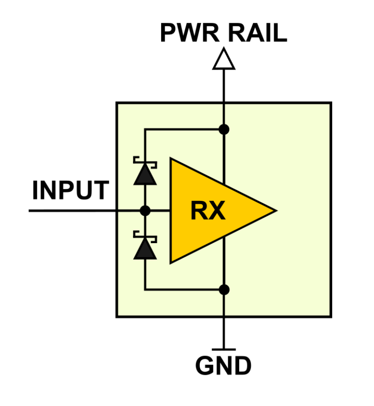
There are various methods that can be used to provide reverse battery protection when designing electrical systems. All of them have the same objective: to prevent the flow of current when the battery terminals are connected in reverse. The most commonly used techniques for reverse input protection are a series diode or a high-side MOSFET switch. By the way, have you ever noticed that car battery cables are designed in such a way that it is practically impossible to connect the batteries in reverse? Always put thought into your design, and make sure there is as little chance as possible of someone messing up the wiring.
Cold crank
Changes in outside temperatures have a significant impact on lead acid batteries, with a possible power loss of up to 70% when exposed to -30°C compared to their power rating at room temperature. Additionally, starting gas engines in cold temperatures requires more power due to the impact of low temperatures on engine oil and mechanical parts. The power required to start an engine at -30°C could be double the power required at a temperature of 20°C. The voltage profile of the battery during cold crank conditions is shown in Figure 3. This profile is described in ISO 7637-2. It specifies test methods and procedures to ensure the compatibility of electrical transients conducted on equipment installed on cars.

To start the engine when it is cold, the starter motor draws a high amount of current from the battery. During cold cranking conditions, the battery voltage may drop below 3 volts for approximately 15 milliseconds. Following that, the battery voltage gradually rises to around 6 volts, where it remains for a few seconds before returning to its normal voltage level.
A voltage drop in a cold crank condition can lead to temporary malfunctions in sensitive electronics like the radio, display, or engine control unit. For this reason, when designing the power supply circuit for electronic equipment, keep in mind that the input voltage might drop as low as 3 volts.
Warm crank
Warm crank refers to the process of starting a car engine that is already warm. Because a warm engine has recently been running, its internal components and fluids will still be warm, making it easier for the starter to turn the engine. The battery will also be warmer, which will increase its capacity compared to cold crank conditions and provide the necessary power to turn over the engine.
A warm crank pulse (Figure 4) is very similar to the cold crank pulse that we discussed before. But in this case, the voltage drop and its duration are typically less severe. During a warm crank pulse, the battery voltage might dip to roughly 6 volts. Following a brief period of around 5 ms, the battery voltage increases to approximately 8 volts. And then, after a second or so, the voltage will return to its nominal value of 12 volts.

A voltage drop in a warm crank, like a cold crank, can cause temporary malfunctions in sensitive electronics such as the radio, display, or engine control unit. A warm crank may occur more often than a cold ignition. This is a particularly common phenomenon in cars with the “star-stop” function. Although the voltage drop is lower in this case than during a cold start, it is necessary to ensure the operation of electrical devices. It’s safe to say that no one would like their screen to flicker and the music to stop when they start their car. For this reason, when designing the power supply circuit for electronic equipment, keep in mind that the input voltage might drop as low as 3 volts.
Load dump
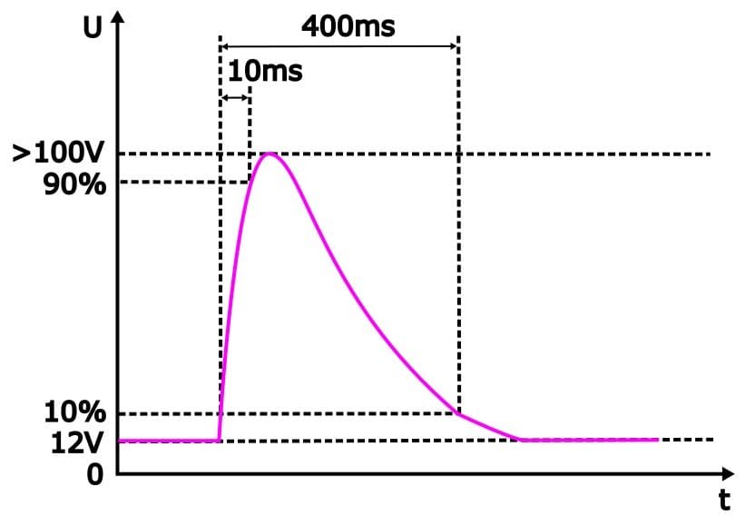
A load dump transient in cars is a sudden surge in voltage that occurs in the electrical system of a vehicle when the alternator is suddenly disconnected from the battery (Figure 5). This can happen, for example, when the battery cable is damaged, corroded, or not tightened properly.

During normal operation, the alternator provides a consistent stream of electrical power to charge the battery and power the vehicle’s electrical systems. However, when the alternator is suddenly disconnected, the electrical energy stored in the alternator’s magnetic field is released into the system, causing a sharp spike in voltage. The peak voltage of the surge can exceed 100 volts, and the surge takes up to 400 ms to decay.
Load dump transient pulses are defined in ISO 16750-2, which we previously mentioned. This standard describes two types of load dump transients: without centralized suppression (unsuppressed) and with centralized suppression (suppressed).
Unsuppressed load dump transients occur when the alternator has no internal clamping to absorb or regulate the voltage spike. This means that the car’s electronics connected to the alternator are subjected to this large transient, shown in Figure 6.
Suppressed load dump transients occur when the alternator has voltage suppression devices in the system that help to absorb and regulate the voltage spike. This results in a clamped waveform, like in Figure 7.

Without load dump protection, a load dump transient could cause significant damage to a vehicle’s electrical system, leading to costly repairs and potential safety hazards. Therefore, load dump protection is an essential feature in modern car electronics design.
Summary
In conclusion, understanding the various electrical phenomena that can occur in a vehicle’s electrical system is crucial when designing automotive electrical circuits. Reverse battery, cold crank, warm crank, and load dump are some of the common issues that can occur in car electrical systems. Each of them has its own unique characteristics and effects. Understanding these issues and taking preventive measures in automotive circuits allows one to extend the life of a vehicle and improve the overall user experience.