High-side current sensing is used in a wide range of applications. Usually, it is used for overcurrent protection in power management circuits. On the market, there are many off-the-shelf operational amplifiers that can be used to measure current on the high-side power bus. However, a problem occurs when current needs to be measured in high common-mode voltage circuits. Here, a simple operational amplifier circuit is not enough. In this article, we will design a low-cost current sensing circuit for systems with high common-mode voltages. The circuit is based on the INA139 current sense amplifier.
How the INA139 works
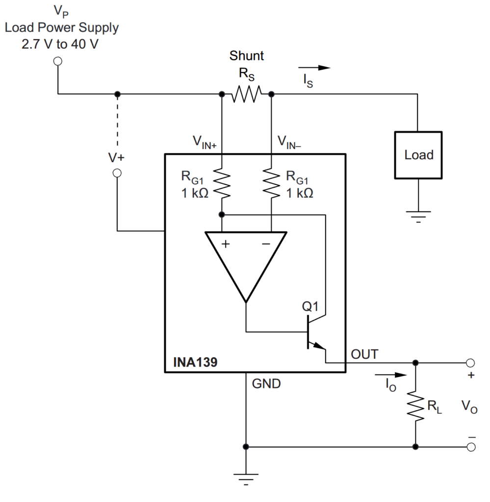
The INA139 is a high-side, unidirectional, current sense amplifier. This device converts a differential input voltage to a current output. The INA139 is designed for current-shunt measurement circuits, as shown in Figure 1. This figure is taken from page 10 of the INA139 datasheets.

Because of its ability to output a current, the INA139 is used in high-side current sensing. The voltage drop over the shunt resistor Rs will generate a higher voltage on the positive input of the internal operational amplifier than on the negative input. The voltage drop in the shunt resistor is forced across the internal resistor RG1 by the internal operational amplifier. This causes current to flow through the Q1 transistor’s emitter and collector. The same current flows through the external resistor RL, and thus the voltage drop through RL is generated. This way, INA139 generates an output current that is directly related to the voltage drop over the shunt resistor.
High-side high-voltage current sensing circuit
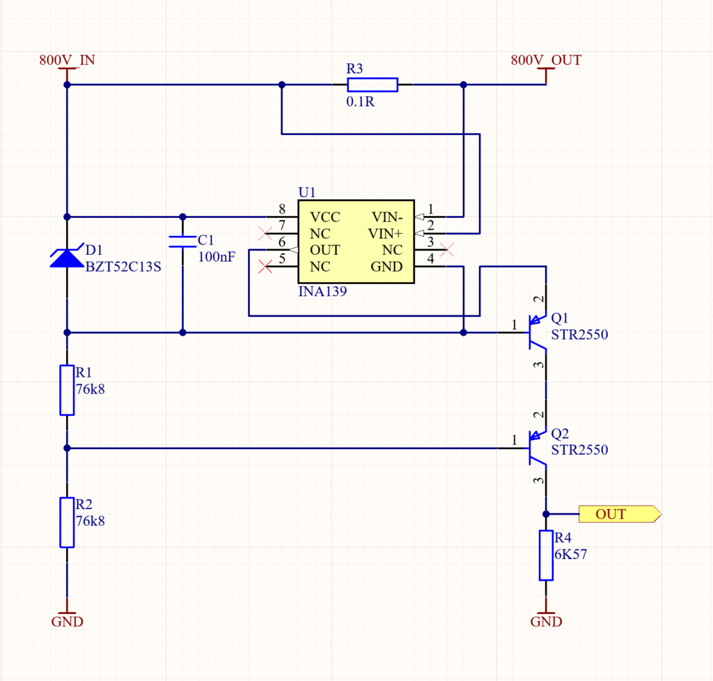
Let’s design a current measuring circuit for systems with high common mode voltages up to 800 volts. The circuit ought to be able to measure current up to 5A. The INA139 has a maximum common-mode voltage of 40V. This means that we somehow need to figure out how to power the IN139 from the high-voltage power rail that we are measuring. Furthermore, the output of this system should be easily measured by a microcontroller. Figure 2 illustrates a low-cost circuit to measure currents with a high common mode voltage. Let’s analyze the circuit and discuss how we came up with it.

In order to use INA139 to measure current at higher voltages, we need it to float near the measurement voltage. In Figure 2, this is done by using a zener diode (D1). The zener diode creates a virtual ground that is always below the common mode voltage. The virtual ground voltage level depends on the zener voltage of the zener diode. Here we are using a BZT52C13S Zener diode, which has a 13V zener voltage. If we connect the power supply (VCC) and ground (GND) pins of the INA139 across the zener diode, we will be able to use the zener diode as a floating power supply. The rest of the voltage will drop over the series resistance (R1 and R2) to ground.
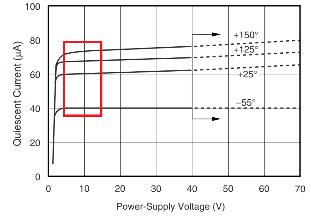
Next, we need to determine the series resistance for R1 and R2. These resistors are the main power consumers due to their voltage drop of up to 787V. If the series resistance is too high, it will not allow the zener diode to avalanche properly. If resistance is too low, resistors will dissipate more power than necessary. According to the INA139 datasheet, the maximum quiescent current at a 5V power supply is 125uA. Figure 3, taken from the INA139 datasheet, shows that the quiescent current at a 13V power supply should not be much higher than at 5V.

Since we know that the zener voltage of a zener diode is 13V and the bias current is 5mA, we can calculate the series resistance using Ohm’s law:
$$R_{1,2}= \frac{V_{CM} – V_{ZENER}}{I_{INA139}+I_{ZENER}}; $$
$$R_{1,2}= \frac{800V – 13V}{125\mu A+5mA}= 153.6k\Omega;$$
In the circuit, we are cascoding transistors. Therefore we will need to use two resistors that, in series, have previously calculated resistance. So for R1 and R2 76.8kΩ resistors should be used.
The circuit uses two PNP transistors (Q1 and Q2) to cascode the INA139 signal. For a lower common mode voltage, one PNP transistor could be used. Here we are using two of them because it is hard to find PNP transistors with a higher collector-emitter breakdown voltage than 500V. The output current of the INA139 will flow through those transistors and create a voltage drop over resistor R4. Voltage over R4 is referenced to the system ground and can be easily measured with a microcontroller.
We must not forget to appropriately choose the shunt resistor R3. From the INA139 electrical characteristics, we know that the maximum full-scale sense voltage is 500mV. Therefore, according to Ohm’s law, to calculate shunt resistance, we just need to divide 500mV by the maximum system load current, which is 5A. We may therefore determine that the shunt resistance should be 100mΩ:
$$R_{3}= \frac{V_{SENSE}}{I_{LOAD}};$$
$$R_{3}= \frac{500mV}{5A}= 100m\Omega;$$
The last thing that we need is to choose an output resistor R4. According to the datasheet, the INA139 has a transconductance of 1000uA/V. Let’s say that we are using a microcontroller with a 3.3V ADC reference voltage. By applying Ohm’s law, we may determine the R4 value. In this case, to determine the value for R4, we need to divide 3.3V by the maximum output current of the INA139.
$$I_{INA139}= 1000\frac{\mu A}{V}\cdot V_{SENSE}= 500\mu A;$$
$$R_{4}= \frac{V_{OUT}}{I_{INA139}};$$
$$R_{4}= \frac{3.3V}{500\mu A}= 6.6k\Omega ;$$
Here the standard resistance value that we can use is 6.57kΩ.


